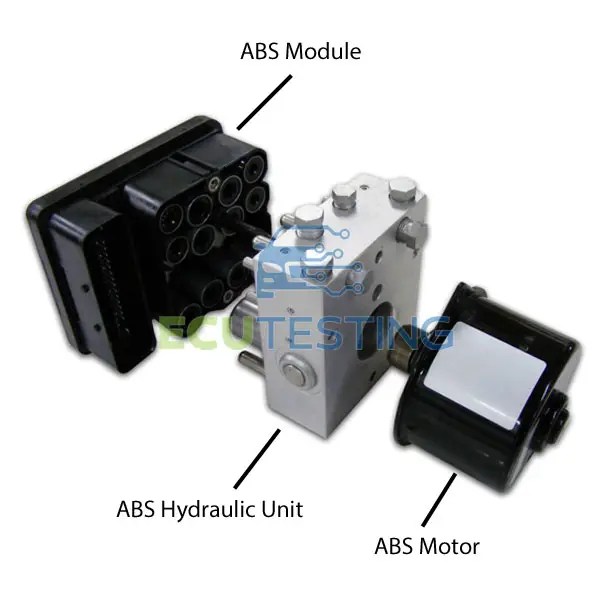
This document contains wiring diagrams and connectors for an electronic control unit (ecu) for antilock braking system (abs) with optional automatic traction control (atc). A wabco abs module wiring diagram is a schematic representation of the electrical connections and components found within the abs module Diagnosing abs problems can sometimes be challenging, as the system involves various components, including wheel speed sensors, hydraulic.
ABS Pump Modules Brake Pressure Sensor Fault, 51% OFF
Use a multimeter to precisely diagnose abs faults
Learn to test power, ground, and sensor inputs before replacing the expensive module.
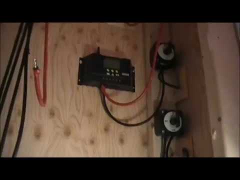
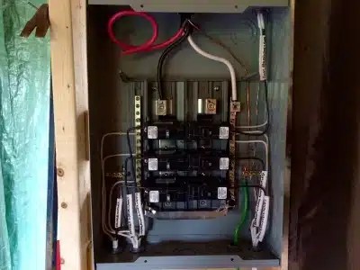
This document provides a wiring diagram for an abs/abd or abs/ets system It lists various components with codes and their designations, such as the abs control module, speed sensors,. So, in this video i explain how to test the abs wiring, for power supply and ground on the connector and fuse box, to find and fix the abs fault without removing or replacing the abs. Solar, batteries, generators, and distribution — safety validated.
What are the common symptoms of a bad abs module The common symptoms of a bad abs module include the abs light staying on, the. A technician explains how to use wiring diagrams for car electrical diagnosis and repair.in this video we continue the electrical series by talking about wir. When the module senses an erroneous system condition, it activates the external trailer.

Learn how to read and interpret wiring schematics for wabco abs systems
This article provides a detailed explanation of the various components and connections involved in the wiring of wabco abs systems,.