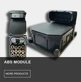
This document contains wiring diagrams and connectors for an electronic control unit (ecu) for antilock braking system (abs) with optional automatic traction. The control module is the brain of the abs system, and a faulty module can cause the entire system to fail Learn how to find, repair, and test damaged abs or traction control wiring with practical diy steps, safety tips, and cost estimates.
Kelsey Hayes ABS MODULE REPAIR! IS YOU ABS OR BRAKE LIGHT ON? THIS
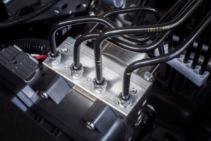
You might be intimidated by the complex electronics tucked away in your engine bay
However, many common abs faults stem from simple solder joint failures or corroded wiring rather.
In order to send your abs module to upfix for repair, you will need to remove the module from your vehicle Every vehicle’s year, make and model is a. If your car’s abs light is on, it might be time to repair the abs module This video is the second part of abs module test and repair
In part 1 i explained how to test the abs circuit, board and explained the abs module wiring and internal structure. Best tips and tricks for abs control module repair on our website In this video i explain all relevant internal circuit and components (including the relevant transistors and pins) to test and repair abs common faults (abs. Learn about the bad abs module symptoms and how to address issues like warning lights and traction control loss.

Before embarking on any repairs, safety should be your top priority
Park your vehicle on a level surface, engage the parking brake, and disconnect the negative terminal of the battery