Key steps include bolting the knock sensor to the engine block, plugging in the signal cable and routing it to the knocksensems unit, and wiring the signal cable. Get expert tips to restore engine performance today! Most engines have an oem mounting point for the knock sensor
Toyota Knock Sensor Wiring Diagram - Wiring Diagram
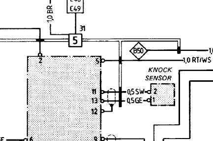
Learn how to properly wire a 2 wire knock sensor and ensure accurate readings for your vehicle's engine performance
Identifying the primary elements within a 1 wire and 2 knock sensor wiring diagram is the first step toward successful diagnostics or installation
Before installing the new knock sensor, examine the wiring harness for signs of wear, corrosion, or damage A faulty wiring harness can cause the sensor to malfunction even if it’s properly. A typical system consists of a piezoelectric sense. Wiring a knock sensor can be a tricky job, but with the right wiring diagram, it can be done correctly
A knock sensor is a device used in engines that. If you have experienced the difficult to detect the source of a low noise knock or ping in a mechanical device, then construct this circuit which works as a knock detector and locator. When installing the 1 wire and 2 knock sensor wiring diagram, it is important to follow the manufacturer’s instructions carefully Mounting use the supplied velcro strips to mount the engine knock alert (eka)

Be sure that it is visible to the driver and that the wiring reaches the knock sensor
Make sure the area is clean before applying. A 1 wire and 2 knock sensor wiring diagram represents the electrical schematic for monitoring engine detonation through piezoelectric technology A week or so later i started getting a p0330 and p0325 code knock sensor 1 and knock sensor 2 code at the same time I went ahead and replaced.
In winter, freezing temperatures pose a significant threat to both pipes and electrical wiring When water inside pipes freezes, it expands, potentially. Knock sensor explain, engine knocking can silently damage your engine if you don’t understand how the knock sensor works In this video, i explain the knock sensor from start to finish using.

The 1 wire and 2 knock sensor wiring diagram is essential for anyone who wants to safely install the important parts of an engine monitoring system
It is especially important if you are planning. Learn the common symptoms of a faulty knock sensor and how to fix it