Identifying the primary elements within a 1 wire and 2 knock sensor wiring diagram is the first step toward successful diagnostics or installation Wiring a knock sensor can be a tricky job, but with the right wiring diagram, it can be done correctly The document provides information about diagnosing a p0325 knock sensor 1 circuit diagnostic trouble code (dtc), including
Interfacing Knock Sensor : Circuit, Code and Its Working
1) the knock sensor detects engine knocking by generating a voltage when.
Key steps include bolting the knock sensor to the engine block, plugging in the signal cable and routing it to the knocksensems unit, and wiring the signal cable connections.
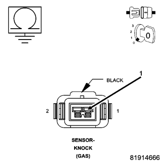
This diagram shows the location of the sensors, their connections, and the power. This guide will go through a knock sensor diagram and its working principles Knock sensors play integral roles in vehicles, and you need to. The wiring diagram of a 1 wire and 2 knock sensor is an important piece of information when it comes to diagnosing problems with your vehicle
Many single wire circuits and some 2 wire circuits utilise a 5v bias voltage from the pcm to the knock sensor and a bleed resistor internal of the knock sensor Knock sensor diagram is a schematic drawing of how a knock sensor works The diagram shows the electrical connections between the knock. Simply wire the sensor pin 1 (left most pin in the below picture) to the knock +ve/knock signal pin and the other pin to ground (sensor ground preferred, such.

That’s why it’s important to use a wiring diagram for your knock sensor
A wiring diagram will show you which wires to connect to each terminal It will also help you identify which wire colors correspond to. The key to correctly wiring a knock sensor is having access to a detailed knock sensor wiring diagram These diagrams provide all the necessary information needed to correctly install the.
I'm using a gte harness on my application which has a map and iat sensor, both which require a sensor ground This is the ground wire that i use to feed the two bosch knock sensors.