Detailed wiring diagram for cam sensors, including color codes and pinouts The process of replacing the camshaft position sensor involves removing the old sensor, installing a new one, and reconnecting the wiring harness A useful guide for troubleshooting and repair of camshaft position sensors.
Camshaft Position Sensor | Function , types ,Working
Learn how a camshaft position sensor works and understand its pinout in just 30 seconds
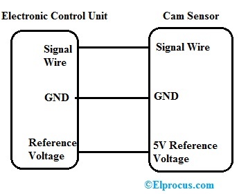
This quick guide covers the 3 main wires
5v supply, signal wire, and ground. Detailed guide on camshaft sensor wiring diagram, explaining connection points, troubleshooting tips, and installation steps for accurate engine sensor readings. This is where understanding the camshaft position sensor wiring really matters This essay will delve into the intricacies of a cmp sensor's wiring diagram, exploring its function, various types, common wiring configurations, troubleshooting techniques, and the importance of accurate.
Camshaft position sensor wiring diagram is a critical component in modern automotive engines, playing a vital role in the engine management system This sensor helps the engine control unit (ecu). Understanding the camshaft position (cmp) sensor wiring harness is crucial for anyone tackling engine diagnostics, repairs, or performance. There are different types of sensors used in automobiles like airflow, engine knock, engine speed, voltage, oxygen, throttle position, camshaft position sensor, map,.

The camshaft sensor wiring diagram generally represents a series of connections which link the camshaft sensor and relevant parts of the engine with.
A camshaft position sensor (cmp sensor) is an electronic device used in modern engines to monitor the position and rotational speed of the. The camshaft position sensor wiring diagram can help you figure out the exact position of each component in the overall system Here is how you can. The easy connection of camshaft position sensor to ecu, ignition coil pack, and to spark plug with check engine revealed.