Detailed wiring diagram for cam sensors, including color codes and pinouts Learn how to test your camshaft position sensor with easy diy steps A useful guide for troubleshooting and repair of camshaft position sensors.
Camshaft Sensor Wiring Diagram - Wiring Diagram
A quick guide to understanding both a two and three wire camshaft position sensor wiring diagram in simple language!
Learn how a camshaft position sensor works and understand its pinout in just 30 seconds
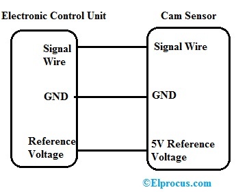
This quick guide covers the 3 main wires 5v supply, signal wire, and ground. This is where understanding the camshaft position sensor wiring really matters Diagram 5 camshaft position s.
The camshaft position sensor, or camshaft sensor, is a crucial component of your engine that determines how and when the spark plugs fire Fortunately, it’s easy to understand cam sensor. The first chapter will explore what camshaft position sensor wiring diagram is, why camshaft position sensor wiring diagram is vital, and how to effectively learn about camshaft position sensor wiring. The camshaft position sensor, a fundamental component within modern internal combustion engines, plays a pivotal role in accurately determining the rotational.
Here you will quickly learn how to test camshaft position sensor with multimeter s, with pictures for 2 and 3 wires!
We have a detailed cmp sensor wiring diagram file ready for you to download This diagram provides a comprehensive view of the. The easy connection of crankshaft position sensor and camshaft position sensor wiring diagram and trouble analysis. 3 wire camshaft sensor connection guide with harness and pin layouts match each lead to its corresponding terminal using the color codes printed on the connector
Black and red usually carry the.