Detailed wiring diagram for cam sensors, including color codes and pinouts A camshaft sensor is a device that monitors the position of the camshaft in an engine A useful guide for troubleshooting and repair of camshaft position sensors.
CAMSHAFT POSITION SENSOR TO ECU WIRING DIAGRAM AND CHECK ENGINE
Diagram 5 camshaft position s.
The camshaft position sensor (cmp), also known as a cam sensor, is a crucial component in modern internal combustion engines
Understanding the wiring diagram for a cmp sensor is essential for accurate diagnostics and effective repairs This essay will delve into the intricacies of these wiring diagrams, explore their significance,. A quick guide to understanding both a two and three wire camshaft position sensor wiring diagram in simple language! This is where understanding the camshaft position sensor wiring really matters
The camshaft position sensor, or camshaft sensor, is a crucial component of your engine that determines how and when the spark plugs fire Fortunately, it’s easy to understand cam sensor. The camshaft sensor wiring diagram generally represents a series of connections which link the camshaft sensor and relevant parts of the engine with. Ever find yourself staring at a camshaft position sensor (cmp sensor) wiring diagram and feeling like you're trying to decipher.
In this guide, we’ll explain what that sensor really does, why you might still see the code after replacing it, and how to perform a proper camshaft position sensor replacement to restore reliable.
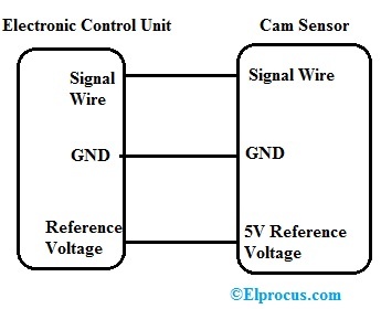
The easy connection of camshaft position sensor to ecu, ignition coil pack, and to spark plug with check engine revealed. There are different types of sensors used in automobiles like airflow, engine knock, engine speed, voltage, oxygen, throttle position, camshaft position sensor, map,. The camshaft position sensor wiring diagram can help you figure out the exact position of each component in the overall system Here is how you can.
The camshaft position sensor (cmp) is a critical component in modern internal combustion engines It plays a vital role in engine management by providing the engine control unit (ecu) with information.