Detailed wiring diagram for cam sensors, including color codes and pinouts The camshaft position sensor wiring diagram is a critical component in modern internal combustion engines A useful guide for troubleshooting and repair of camshaft position sensors.
Camshaft Sensor Wiring Diagram Guide
A quick guide to understanding both a two and three wire camshaft position sensor wiring diagram in simple language!
This is where understanding the camshaft position sensor wiring really matters
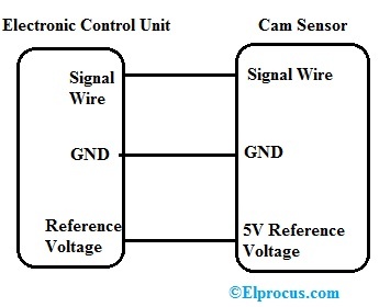
Camshaft position sensor wiring diagram is a critical component in modern automotive engines, playing a vital role in the engine management system This sensor helps the engine control unit (ecu) determine. The camshaft position sensor (cmp), also known as a cam sensor, is a crucial component in modern internal combustion engines The camshaft position sensor, or camshaft sensor, is a crucial component of your engine that determines how and when the spark plugs fire
Fortunately, it’s easy to understand cam sensor. This essay will delve into the intricacies of a cmp sensor's wiring diagram, exploring its function, various types, common wiring configurations, troubleshooting techniques, and the importance of accurate wiring. The camshaft sensor wiring diagram generally represents a series of connections which link the camshaft sensor and relevant parts of the engine with. Ever find yourself staring at a camshaft position sensor (cmp sensor) wiring diagram and feeling like you're trying to decipher.
The camshaft position sensor and its wiring are fundamental to the functioning of modern internal combustion engines
A good understanding of how the sensor works and common wiring issues will. The camshaft position sensor, a fundamental component within modern internal combustion engines, plays a pivotal role in accurately determining the rotational. The camshaft position sensor wiring diagram can help you figure out the exact position of each component in the overall system Here is how you can.