In this video, you'll learn the wiring connections of 3 and 4 wire iac valve (idle air control valve). The duty cycle frequency of an idle air control valve solenoid is about 100 hz, other motor. This article explains the most common types of idle air control valves and how to wire them up using a haltech nexus or elite ecu
Idle Air Control Valve - 1AISC00003 at 1A Auto.com
This type of idle valve is the simplest to wire up, being a solenoid with just.
Sound or visuals were significantly edited or digitally generated
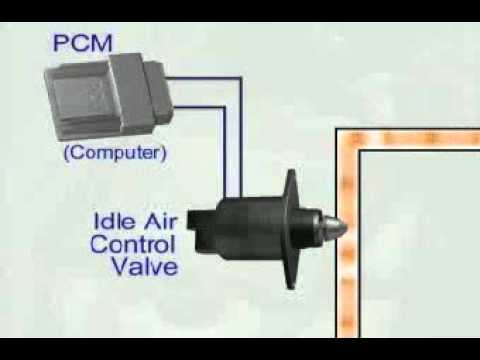
Having an accurate idle air control valve wiring diagram is crucial for properly diagnosing iac issues With a complete diagram, you can easily identify. An idle air control valve wiring diagram is a specialized schematic illustrating the electrical connections between the engine control unit (ecu) and the idle air control actuator. Improve your automotive skills today
Understand symbols, wire colors, and connectors while learning how to diagnose and repair electrical. They provide detailed instructions for service schedules, maintenance, wiring diagrams, and diagnostics, ensuring that you can perform tasks ranging from simple air filter changes to complex engine. Repair & service guides → how an engine idle air control valve works how an engine idle air control valve works when an idle air control valve fails it can. An idle air control valve regulates how much air enters your engine when you're stopped at a red light or parked with the engine running, ensuring stable rpm and preventing stalling

Find out how to recognize symptoms of a faulty idle air control valve (iac valve), diagnose the issue, and replace it effectively with autozone.
I need a wire diagram for the idle air control valve that looks similar to the picture below so i can trace those wires and see if there is power or continuity. When you need to diagnose a problem with your toyota vehicle, a toyota idle air control valve wiring diagram can be an invaluable tool Resetting the idle air control valve is a straightforward process that anyone can do at home with just a few simple tools However, if you’re not confident in your ability to do so, it’s always best to consult a.
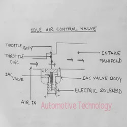
An idle air control valve diagram displays the internal plunger, spring, and electrical connector within the throttle body assembly In this measurement, the used idle air control valve has 2 solenoids