What are the steps to inspect the operation of the idle air control (iac) valve on the 2rz−fe or 3rz−fe engine, and what issues might arise if the inspection results. Having a diagram that clearly illustrates the components of the idle air control valve wiring system is essential for diagnosing and repairing the problem. This article explains the most common types of idle air control valves and how to wire them up using a haltech nexus or elite ecu
Air Control Valve Wiring Diagram
This type of idle valve is the simplest to wire up, being a solenoid with.
In this video, you'll learn the wiring connections of 3 and 4 wire iac valve (idle air control valve).
An idle air control valve wiring diagram is a specialized schematic illustrating the electrical connections between the engine control unit (ecu) and the idle air control actuator. Having an accurate idle air control valve wiring diagram is crucial for properly diagnosing iac issues With a complete diagram, you can easily identify. Rely on cummins manuals and technical documents for dependable support
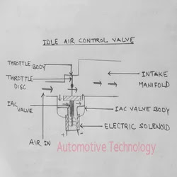
Find documents and materials for your cummins products. Sound or visuals were significantly edited or digitally generated The document discusses idle air control systems which regulate engine idle speed by adjusting the volume of air that bypasses the closed throttle valve An idle air control valve regulates how much air enters your engine when you're stopped at a red light or parked with the engine running, ensuring stable rpm and preventing stalling

In today’s video, jake explores the idle air control (iac) valve, an integral component of your vehicle's engine management system.
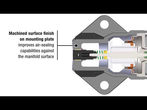
An idle air control valve diagram displays the internal plunger, spring, and electrical connector within the throttle body assembly It shows how the engine. With a lab scope an idle air control valve signal voltage is measured under various conditions The signal from the actuator is shown and can be downloaded
Learn how the different types of idle air control valves work and their importance in maintaining engine performance at idle. A detailed explanation of the idle control valve diagram, its components, and how it functions in vehicle engine systems Understand its role in maintaining optimal. For example, the diagram helps identify where the mass air flow (maf) sensor or idle air control (iac) valve is positioned

Knowing their location allows you to inspect, clean, or replace these parts without.