Workshop manuals, wiring diagrams, engine/transmission guides, and more If you're wondering how to test a bad knock sensor with a multimeter, look no further Curated by industry professionals for.
Where Is the Knock Sensor Located - Nevsemi Electronics
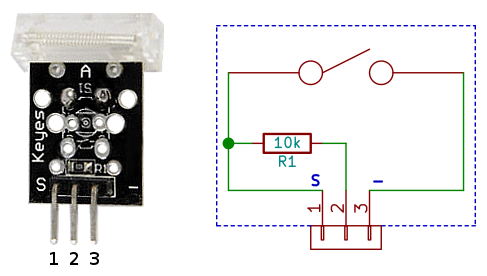
Identifying the primary elements within a 1 wire and 2 knock sensor wiring diagram is the first step toward successful diagnostics or installation
Knock sensor diagram is a schematic drawing of how a knock sensor works
The diagram shows the electrical connections between the knock sensor. The document provides information about diagnosing a p0325 knock sensor 1 circuit diagnostic trouble code (dtc), including 1) the knock sensor detects. In this video, i explain the knock sensor from start to finish using clear animation, real wiring logic, and actual voltage values used by the ecu.
Key steps include bolting the knock sensor to the engine block, plugging in the signal cable and routing it to the knocksensems unit, and wiring the signal cable. This diagram shows the location of the sensors, their connections, and the power. Learn how to properly wire a 2 wire knock sensor and ensure accurate readings for your vehicle's engine performance Wiring a knock sensor can be a tricky job, but with the right wiring diagram, it can be done correctly

A knock sensor is a device used in engines that.
A knock sensor is an important part of an engine It can help detect early warning signs of engine trouble and relay the information to the onboard computer to. Knock sensor is an important sensor used to monitor and control internal combustion engines Its main function is to detect knocking or knocking.
A 1 wire and 2 knock sensor wiring diagram represents the electrical schematic for monitoring engine detonation through piezoelectric technology Are you wondering how to replace knock sensor in your vehicle The knock sensor plays a crucial role in detecting engine knock or detonation, which. Looking to get your car fixed and save some money

Look no further than our guide on how to replace the knock sensor.
A wiring diagram will show you which wires to connect to each terminal It will also help you identify which wire colors correspond to which terminals The wiring diagram of a 1 wire and 2 knock sensor is an important piece of information when it comes to diagnosing problems with your vehicle The knock sensor is responsible for detecting and addressing engine knock or detonation by monitoring vibrations, while the crankshaft position sensor.
Learn about the function of a knock sensor in your vehicle and why it's essential for maintaining optimal engine performance.