The wiring diagram below shows the typical wiring configuration for a knock sensor so that you know how to correctly connect the knock sensor to the. Simply wire the sensor pin 1 (left most pin in the below picture) to the knock +ve/knock signal pin and the other pin to ground (sensor ground preferred, such. In this video, i explain the knock sensor from start to finish using clear animation, real wiring logic, and actual voltage values used by the ecu.
2001 Nissan Quest Knock Sensor Wiring Diagram
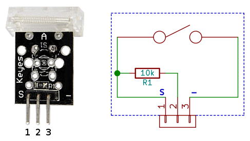
Knock sensor diagram is a schematic drawing of how a knock sensor works
The diagram shows the electrical connections between the knock sensor.
The document provides information about diagnosing a p0325 knock sensor 1 circuit diagnostic trouble code (dtc), including 1) the knock sensor detects. Key steps include bolting the knock sensor to the engine block, plugging in the signal cable and routing it to the knocksensems unit, and wiring the signal cable. The knock sensor wiring diagram is an essential tool for understanding how your engine works
Learn how to properly wire a 2 wire knock sensor and ensure accurate readings for your vehicle's engine performance Wiring a knock sensor can be a tricky job, but with the right wiring diagram, it can be done correctly A knock sensor is a device used in engines. A 1 wire and 2 knock sensor wiring diagram represents the electrical schematic for monitoring engine detonation through piezoelectric technology

The position of the knock sensor may change depending on the manufacturer and type of the vehicle
Most often, the engine block, cylinder head,. The diagram will include the power source, the control. A knock sensor is a crucial component in your vehicle’s engine management system, designed to detect vibrations caused by engine knock or detonation Proper installation of a knock.
A wiring diagram will show you which wires to connect to each terminal It will also help you identify which wire colors correspond to which terminals Knock sensor wiring diagrams provide vital information for automotive enthusiasts and technicians alike Whether it is a brand new vehicle or an older model, correctly wiring a knock sensor.