A 1 wire and 2 knock sensor wiring diagram represents the electrical schematic for monitoring engine detonation through piezoelectric technology. A rat chewed the wire for the original knock sensor In this video, i explain the knock sensor from start to finish using clear animation, real wiring logic, and actual voltage values used by the ecu.
Knock Sensor : Circuit, Working, Types & Its Applications
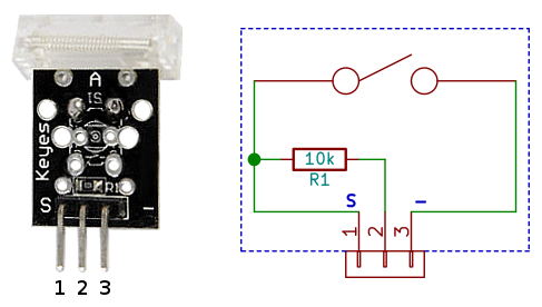
Knock sensor diagram is a schematic drawing of how a knock sensor works
The diagram shows the electrical connections between the knock sensor.
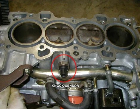
The document provides information about diagnosing a p0325 knock sensor 1 circuit diagnostic trouble code (dtc), including 1) the knock sensor detects. Key steps include bolting the knock sensor to the engine block, plugging in the signal cable and routing it to the knocksensems unit, and wiring the signal cable. Learn how to properly wire a 2 wire knock sensor and ensure accurate readings for your vehicle's engine performance
At its most basic, the 1 wire and 2 knock sensor wiring diagram consists of two main parts The 1 wire and the 2 knock sensor Wiring a knock sensor can be a tricky job, but with the right wiring diagram, it can be done correctly A knock sensor is a device used in engines.

A wiring diagram will show you which wires to connect to each terminal
It will also help you identify which wire colors correspond to which terminals A knock sensor is an important part of an engine It can help detect early warning signs of engine trouble and relay the information to the onboard computer to. Detecting engine knocking is a crucial aspect of ensuring optimal engine performance and preventing potential damage
The knock sensor plays a. The knock sensor detects vibrations that come from a knock or an irregularity in combustion and send a signal to the engine. Replacing a knock sensor ensures your vehicle’s engine runs smoothly and efficiently The knock sensor is a crucial component of the engine.

Knock sensor definition an electronic control system of the engine or listening device on the engine that detects the vibrations and sounds coming from.
If you know for sure where it (or they) are mounted. Knock sensor is the knocking phenomena sensing sensor that helps the engine from getting damaged by the knocking and to improve engine performance A knock sensor is designed to detect abnormal combustion phenomena known as knocking Learn its diagram, construction, working, advantages and applications.